Why I built it
I reduced the interface to hardware that remains understandable at very low resolution: 165 LEDs, directional controls, one confirmation button and physical motion. The result is small enough to live on a keychain without turning every game into the same blinking square.
The design started with a severe interface budget: a 15 × 11 display, five buttons, a buzzer and motion sensing, all in roughly 35 mm square and powered from a coin cell. Every menu and game mechanic therefore had to earn its pixels and its current draw.
The matrix is charlieplexed rather than driven by a large display IC. That saves board area, but it moves complexity into scanning, brightness control and pin-state safety. Each illuminated LED needs one driven pair while the other matrix lines stay high impedance; an incorrect pin state can create a ghost path through LEDs that were meant to be off.
Build diary
Fitting a console into 165 pixels
- Fix the physical pixel budgetStep 1
I committed to the 15 × 11 matrix and 2 mm LED pitch first, then designed icons and game screens at that exact resolution instead of shrinking desktop artwork afterwards.
- Allocate the charlieplex networkStep 2
Fourteen matrix lines were arranged to address the LEDs while leaving enough MCU pins for five independent buttons, the buzzer, IMU and light sensing.
- Choose interactions that survive low resolutionStep 3
Directional buttons handle exact input, while tilt, shake and rotation give the IMU a reason to exist in games such as the sand simulation and dice mode.
- Plan deterministic firmwareStep 4
Display scanning, button polling, game updates and buzzer timing were separated so a slow game routine cannot leave the matrix flickering or a note stuck on.
- Assemble and light the first boardStep 5
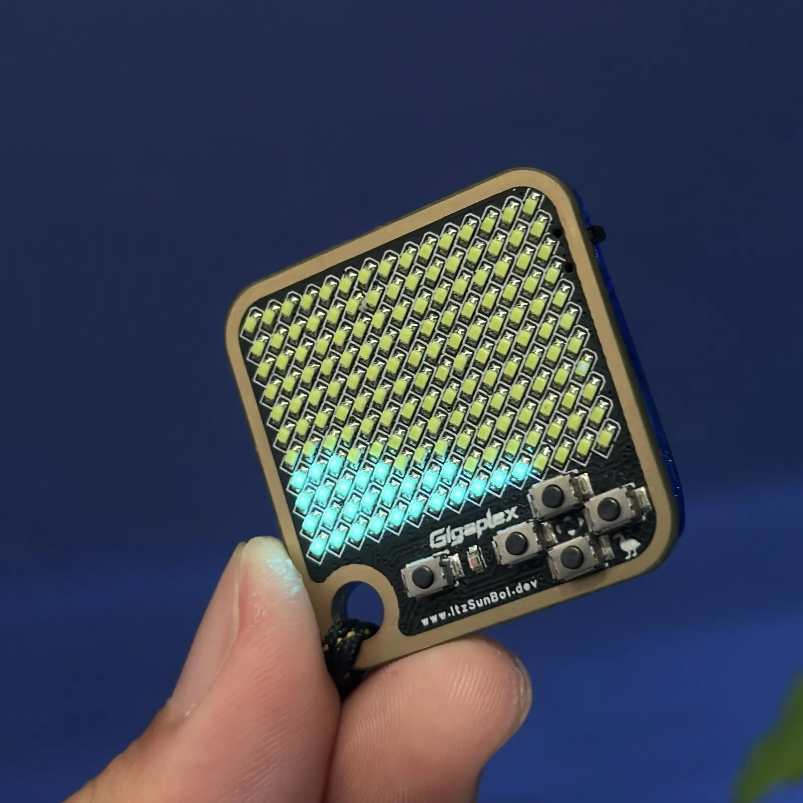
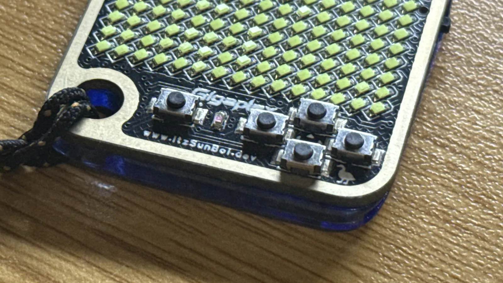
I assembled the populated board with its five switches, keyring opening and rear battery holder. A lit section of the matrix gives me a real electrical bring-up point to inspect.
- Finish the console and packagingStep 6
I finished the console after the first board bring-up and completed its packaging around the keychain-sized hardware.
- Move into mid-scale productionNow
I am moving the finished design toward mid-scale production, where repeatable assembly, inspection and packaging are the next practical constraints.
| Controller | CH32V006K8U6 |
|---|---|
| Display | 15 × 11 charlieplexed LED matrix |
| Input | Five buttons and a 6-axis IMU |
| Audio | Piezo buzzer |
| Power | CR2032 coin cell |
| Board size | Approximately 35 × 35 mm |
The firmware architecture separates matrix scanning, input polling, game state and buzzer timing so the tiny MCU can keep the display stable while games and IMU-driven effects run.
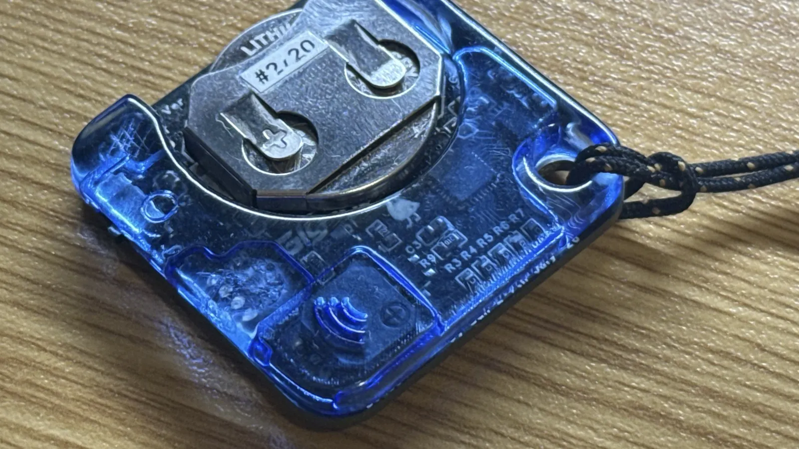
I kept the physical layout within the same tight budget as the code. The five switches sit directly below the LED field, while the keyring hole shares a corner of the board. On the back, the coin-cell holder occupies most of the available area; the translucent blue case follows that outline without hiding the battery access.
Problems, decisions and small fixes
The menu was harder than the games. At this resolution two icons that look distinct on a monitor can merge after the real LED pitch, diffusion and viewing distance are considered, so I repeatedly simplified silhouettes and increased empty space.
Memory is another design constraint rather than a late optimisation. Frame data, games and audio must share a small MCU, which is why the video experiments use compact row and delta commands and a deterministic integer-only decoder.
I could not treat the coin cell like a bench supply. I designed the scan pattern and brightness levels around short, controlled LED drive intervals so the display remains stable alongside the buzzer and IMU without asking the CR2032 for a continuous full-frame load.
Finished build and production handoff
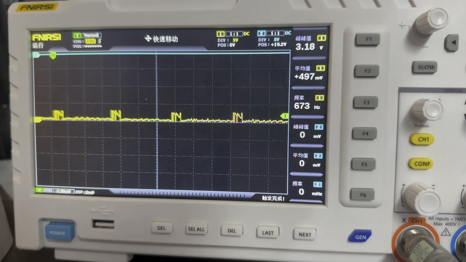
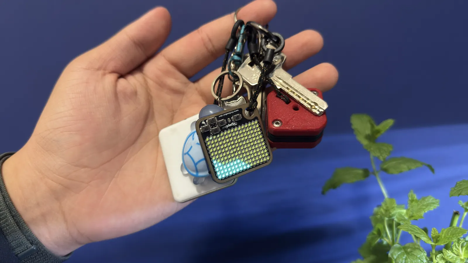
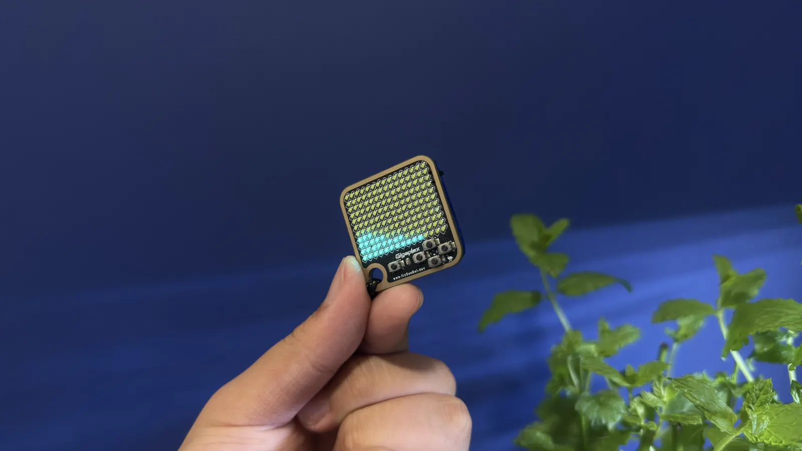
I used the oscilloscope to inspect the short drive pulses behind the display scan during bring-up. The trace records that electrical work; the photographs show the finished front, controls, battery side and case together as a keychain console.
I wanted the console to feel deliberately tiny rather than compromised. With the product and packaging finished, the next challenge is repeating the build: placing 165 LEDs consistently, checking the assembled matrix and controls, and fitting the case without hand-tuning each unit.